Linienförmige Zugbeeinflussung (LZB)
Overview
The Linienförmige Zugbeeinflussung (LZB) is a continuous automatic train control system used to ensure safe and efficient operation at high speeds. Unlike the Punktförmige Zugbeeinflussung (PZB) (see PZB), which transmits discrete signal information at fixed track points, the LZB enables continuous bi-directional data exchange between the train and the trackside control center. This allows for real-time supervision of speed and position and forms the basis for cabin signalling at speeds exceeding 160 km/h.
System Structure
The LZB consists of three main components (DB, 2019):
Trackside Equipment
The track contains cable loops laid between the rails, divided into multiple segments.
These loops enable continuous communication between the train and the LZB control center.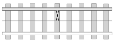
Source: Pachl (2022)
Train Equipment
Each LZB-equipped vehicle has an onboard unit that:- continuously determines the train’s position,
- receives and interprets control information from the LZB center,
- calculates braking curves and speed supervision data,
- and automatically applies braking if limits are exceeded.
LZB Control Center
The control center transmits Movement Authorities (MAs) to the trains within the controlled area, defining:- the permissible target distance,
- the permitted speed at each section,
- and other route-specific properties like gradients
Functionality
During operation, the train continuously reports its position to the LZB center. In return, it receives updated target data like setpoint speed (\(v_{set}\)), target speed (\(v_{target}\)) and target distance.
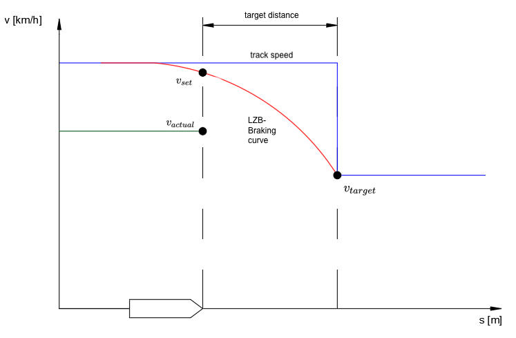
based on: Pachl (2022)
The onboard unit calculates braking curves for different supervision thresholds:
- Permitted Speed Curve – permissible maximum speed at each position. This is the curve the driver train should follow.
- Warning Curve - gives an acoustic warning to the driver when the permitted speed curve is exceeded by 5 km/h.
- Emergency Brake Curve – triggers an emergency brake if the train fails to decelerate sufficiently.
The braking curve that is set by the onboard unit is based on:
- maximum track speed
- slope¹
- braking percentage of the train
The next target point is displayed up to 10.000 m in front of the train. The speed limit equals the maximum track speed or the maximum possible speed of the train itself. (Murr, 1991)
Braking Curves
For LZB there exist twelve braking curves with values between 0,115 und 1,10 m/s². The value of the emergency braking curve is about 40% higher than the permitted speed curve.
The deceleration of the individual braking curves remains constant across the entire speed range.
| Braking Curve Nr (BRN) | A | B | 1 | 2 | 3 | 4 | 5 | 6 | 7 | 8 | 9 | 10 |
|---|---|---|---|---|---|---|---|---|---|---|---|---|
| Emergency Braking Curve [m/s²] | 0,115 | 0,2 | 0,29 | 0,375 | 0,460 | 0,545 | 0,63 | 0,715 | 0,8 | 0,9 | 1,0 | 1,1 |
| Permitted Speed Curve [m/s²] | 0,08 | 0,14 | 0,21 | 0,27 | 0,33 | 0,39 | 0,45 | 0,51 | 0,57 | 0,64 | 0,71 | 0,79 |
based on: Braun (1988)
The illustration below shows the braking curves for BRN 6 as an example.
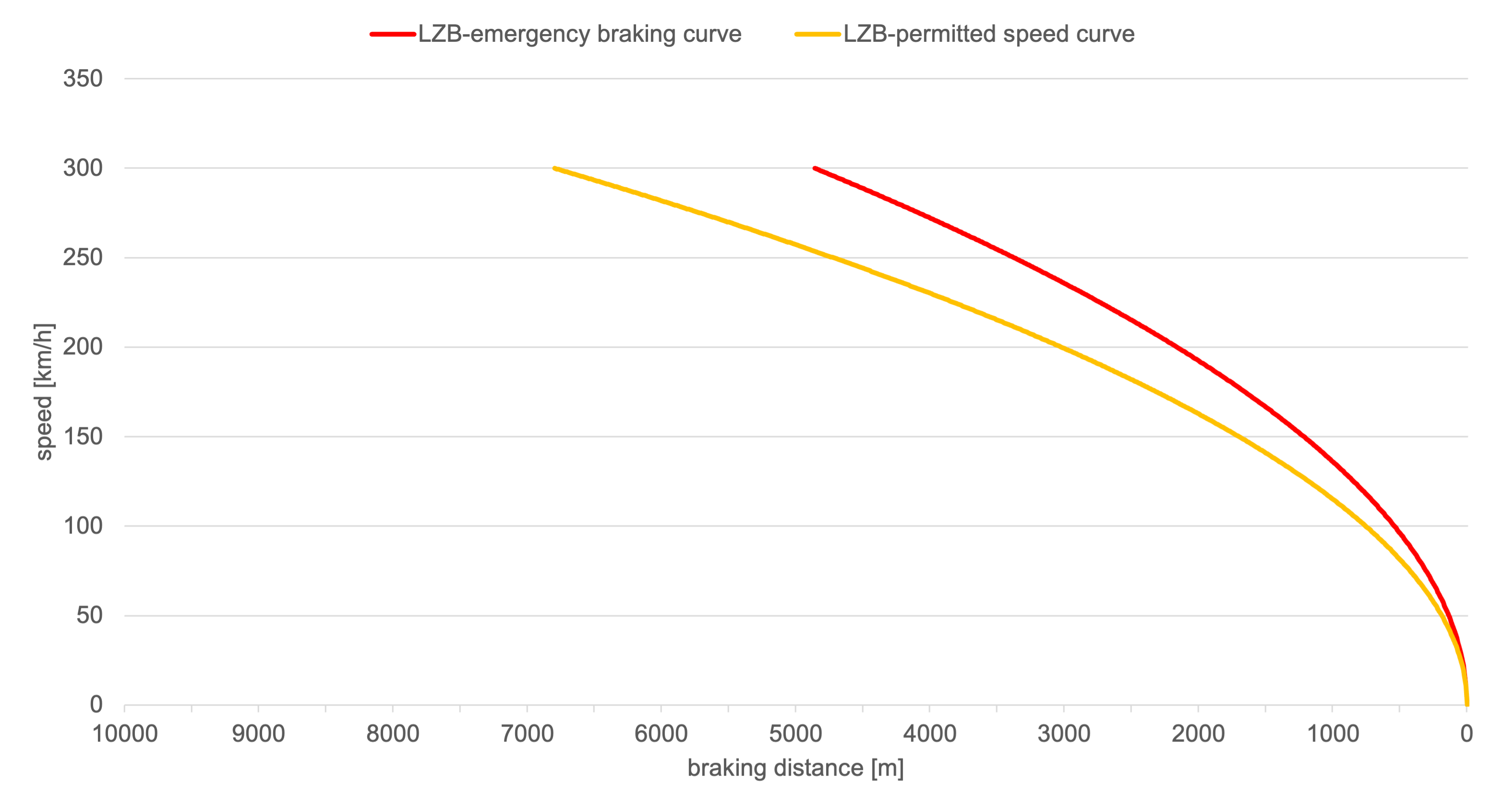
The train driver enters the permissible speed and the brake percentage into the vehicle device. The gradient is specified for the route. The LZB uses this data to set the necessary braking curve. (Braun, 1988)
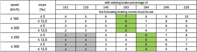
For Passenger trains the following curves must be set:
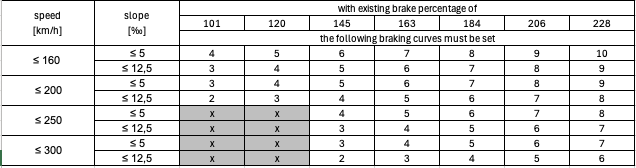
based on: Braun (1988)
For freight trains the following curves must be set:
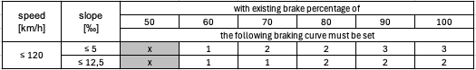
based on: Braun (1991)
Where an “x” is written the combination of braking percentage and speed must not be possible.
Full Block and Partial Block Mode
The LZB can operate in two different control modes: Full Block Mode (german: Ganzblockmodus) and Partial Block Mode (german: Teilblockmodus). Both modes determine how the track is divided into supervised sections and how the control center grants Movement Authorities (MAs) to trains.
In Full Block Mode, each train occupies an entire block section, similar to traditional fixed-block signalling systems. A new train is only allowed to enter a block once the preceding train has completely cleared it. This mode ensures maximum safety but limits the line capacity. (Pachl, 2022)
In Partial Block Mode, the LZB subdivides a block into several smaller LZB subsections. Each subsection can be individually monitored and released as the train progresses, allowing the following train to enter the same block earlier. This dynamic release mechanism increases line capacity significantly while maintaining safe separation between trains. (Pachl, 2022) The partial block principle thus enables higher traffic density and shorter headways, which are especially important for high-speed or high-frequency railway operations. The typical length of a LZB subsection is about 1200 m (Busse, 2021)
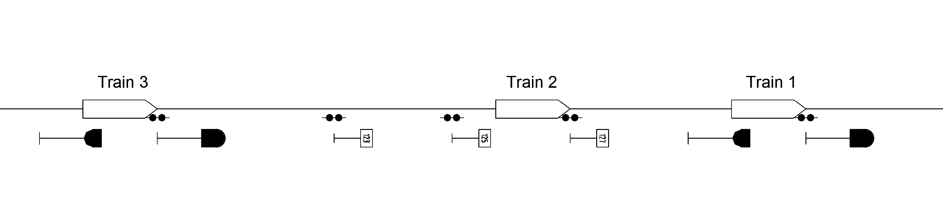
The picture below shows the Partial Block Mode. Train 1 occupies the block between the two main signals. Train 2 is a LZB train and is therefore allowed to enter the block until the section marker. Train 3 is not equipped with LZB and is therefore not allowed to enter the occupied block.
OSRD-modeling
Braking curve is based on the permitted speed curve.
Warning curve and emergency braking curve are not modeled.
The braking curve is constant over the whole braking distance.
The constant deceleration is used for braking to a full stop, for speed changes and for the spacing and routing requirements.
For Partial Block Mode, LZB section markers are placed at the entry of LZB subsections.
Switches are released when the following detector is crossed.
There are no overlaps implemented yet (only affects blocking time).
Simplifications and Assumptions
All LZB-trains have a sight distance of 10.000 m (impacts the distance for average slope calculation, and maybe future work on dynamic simulation).
The slope used to choose the braking curve is the average slope calculated within these 10.000 m.
The train follows the permitted speed curve and does not brake earlier.
OSRD trains do not have brake percentage values, so an alternative to define the used braking curves was used:
- The braking curves are picked depending on the rolling stock category, the train’s maximum speed and the average slope (exact modeling and code to be determined).
Determination of the braking curve
The average deceleration of each speed category was calculated and the corresponding braking curves were chosen. The resulting curves are also the ones that are used the most.
The resulting curves for ≤ 200 and ≤ 250 km/h were the same so they were put together in one category
This results in the following braking curves that must be set for passenger trains:
Slope [‰] ≤ 160 km/h 160 - 250 km/h 250 - 300 km/h ≤ 5 7 6 5 ≤ 12,5 6 5 4 The corresponding deceleration (permitted speed curve) values that must be set for passenger trains depending on the maximum train speed and slope are as follows:
Slope [‰] ≤ 160 km/h 160 - 250 km/h 250 - 300 km/h ≤ 5 0,57 0,51 0,45 ≤ 12,5 0,51 0,45 0,39 possible further simplification for OSRD: deceleration in other LZB-modeling tools is 0,5 for all passenger trains
For freight trains only two decelerations (permitted speed curve) were chosen. They cover all the relevant cases for freight trains with LZB.
Slope [‰] ≤ 120 km/h ≤ 5 0,33 ≤ 12,5 0,27 possible further simplification for OSRD: deceleration in other LZB-modeling tools is 0,3 for all freight trains
References
- Alfred Braun. „Aufstellen von Bremstafeln für Strecken mit Linienzugbeeinflussung“. In: ZEV Glasers Annalen 4 (1988), S. 108–118.
- Alfred Braun. “Die LZB-Bremstafeln für Güterzüge”. In: Eisenbahningenieurkalender (1991), S. 275-282
- DB AG. Ril 819.1320 LZB; Grundsätze für die Ausrüstung mit linienförmiger Zugbeeinflussung. Dez. 2019.
- Eduard Murr. „Systembeschreibung der Linienzugbeeinflussung (LZB) der Deutschen Bundesbahn“. In: Eisenbahningenieurkalender (1991), S. 285–317.
- Jörn Pachl. Systemtechnik des Schienenverkehrs: Bahnbetrieb planen, steuern und sichern. de. Wiesbaden: Springer Fachmedien Wiesbaden, 2022.
- Matthias Busse. „Der optimierte Einsatz von ETCS-Bremskurven“. Dissertation. Dresden: Technische Universität Dresden, Feb. 2021.
¹ The slope is saved in the LZB-Control Center. We don’t yet have reliable information on how the slope in front of the train is calculated, when determining the braking curve.