The onboard computer of ETCS-enabled trains has to compute a number of position / speed curves.
Here is how it works:
below all the curves, the speed indicator is white
above the indication curve, the speed indicator is yellow
above the permitted curve, the speed indicator is orange
above the warning curve, an alarm rings
above the intervention curves, an emergency break intervention is triggered
Inputs
In order to compute any of these curves, a number of things are needed:
target data (the destination of the braking curve, which can be EOA and SvL or LOA and MRSP)
train data
infrastructure data
infrastructure manager constants
standardized constants
Train
max speed
length
rotating mass
T_traction_cutoff: the time it take to cut off traction
braking model, either lambda or gamma:
lambda (braking weight/mass)
gamma (constant deceleration at a given speed)
correction factors (k_dry and k_wet for gamma braking) for braking curves
Infrastructure
corrected gradients (it incorporates curvature)
odometry balise locations
Processes
Braking coefficients:
A_brake_emergency is the expected emergency braking capability, without safety margins
A_brake_safe is the emergency braking coefficient, with safety margins
A_brake_service is the expected service braking capability, without safety margins
Speed / distance targets
EOA end of movement authority: the location until which the train is allowed to move
SvL supervised location: the protected location
Curves
SBD supervised braking deceleration: intermediary result computed from EOA and A_brake_service
EBD emergency braking deceleration: intermediary result computed from SvL and A_brake_safe
All the curves below are cut below a given release speed:
EBI (emergency break intervention) computed from EBD, shifted in position and space given rolling stock metadata
SBI1 computed from SBD, shifted in time with Tbs1
SBI2 computed from SBD, shifted in time with Tbs2
FLOI (also called SBI, the intervention curve) the minimum of SBI1 and SBI2
WARNING (warning curve) computed as a shift of FLOI by Twarning
PS (permitted speed curve): shift of WARNING by time Tdriver
INDICATION is a shift of PS by time Tindication
4.3 - Ks Signalling
The Ks-system (Ks = Kombinationssignal; engl: combination signal) is a german signalling system introduced in 1994 by Deutsche Bahn (DB) in order to create a common system for East Germany (Hl-System) and West Germany (H/V-System) after the german reunification.
The following paragraphs are mainly based on Pachl(2024), Railway Signalling Principles, Edition 3.0, p.20-30.
Block Section Principles
Railway lines are segmented into sequential block sections, each designed to be occupied by only one train at a time to ensure operational safety.
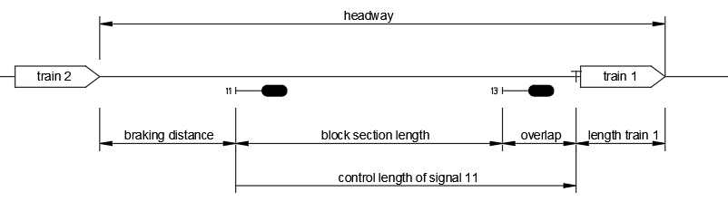
To maintain a safe distance between two trains, the separation must account for the following components:
the braking distance of the following train,
the full length of the block section,
an additional block-extension safety margin, referred to as the overlap
Block sections are delineated by main signals, which regulate train entry based on specific safety conditions. A signal may only be cleared for a train to enter a block section if all of the following criteria are met:
the preceding train has vacated the block section in question
the overlap beyond the next signal has also been cleared by the preceding train
the preceding train is secured by a stop signal
the switches for the route to be set must be locked in the correct position
on lines with bidirectional traffic, the train must additionaly be protected against any potential opposing movements
based on: Pachl (2024), Railway Signalling Principles
Signal control length and overlap principles
The control length of a signal refers to the section of track beyond the signal that must be verified as clear and safe before the signal can be set to proceed.
The overlap - a predefined safety margin - extends beyond the actual block section. Its primary function is to provide additional protection in the event that a train fails to stop at a signal displaying “stop”. The overlap begins at the destination signal and ends at a prominent point. Depending on the speed at which the train approaches the stop signal, different lengths of overlaps must be provided. The length of the overlap is monitored by track vacancy detection systems like axle counters.
speed [km/h]
overlap [m]
60 < v <= 160
200
40 < v <= 60
100
v <= 40
50
A signal must remain at “stop” until the entire control length ahead is confirmed to be unobstructed. The clearing point for a signal corresponds to the end of the control length associated with the signal located behind it.
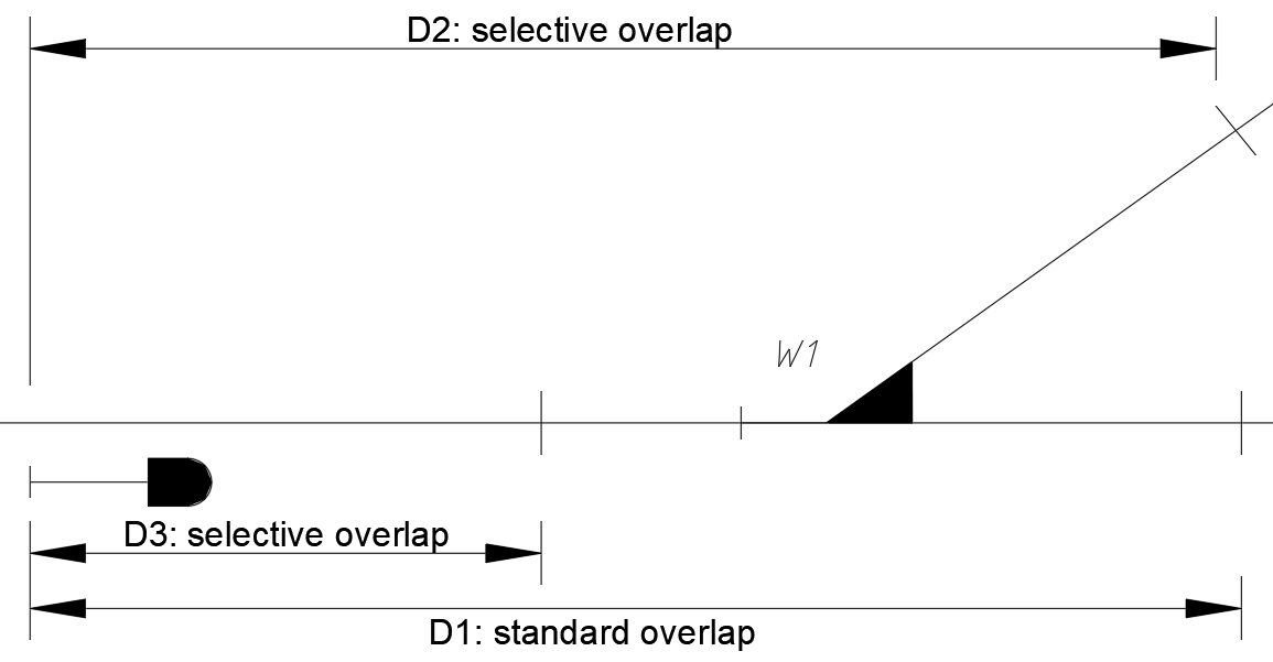
Selective Overlaps
When selective overlaps are available (only at station’s exit signals and station’s intermediate signals) different overlap options can be chosen during route setting. These alternatives may vary in length or lead into different track sections.
An exit signal is the last signal within a station that serves to secure the exit to the free route.
An intermediate signal is set up in extensive station areas between the entry signal and the exit signal and delimits a station section within the station.
Once the signal has been cleared, the selected overlap cannot be changed without first cancelling the route.
If a shorter-than-standard overlap is selected, the signalling system will reduce the train’s speed accordingly.
based on: DB AG, Ril 819.0202 Signale für Zug- und Rangierfahrten
Signal Indications in Ks-System
The Ks-signalling system utilizes a set of standardized signal aspects to convey operational instructions to train drivers. The primary signal indications include:
Stop (Hp 0): The train must come to a complete stop at the signal.
Expect stop (Ks 2): The train must be prepared to stop at the next main signal.
Clear (Ks 1): The train is permitted to proceed.
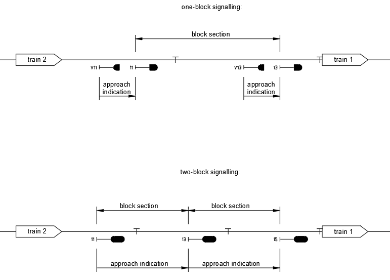
Within the Ks-system two signalling modes are implemented:
One-Block Signalling
The aspect displayed by a main signal is determined by the status of the immediately following block section.
Each main signal is paired with a distant signal that provides the necessary approach indication.
The distant signal is positioned at a distance corresponding to the braking distance from the associated main signal.
Multi-Block Signalling (Two-Block Signalling is used by DB)
The indication of a main signal is based on the status of two consecutive block sections ahead
This approach allows for more dynamic and anticipatory signalling, enhancing operational efficiency and safety
based on: Pachl (2024), Railway Signalling Principles
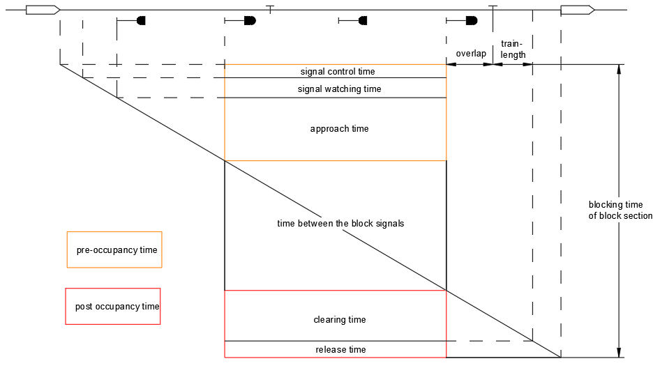
Blocking time model
To ensure undisrupted train movement, a signal must be cleared before the approaching train reaches a point where it would otherwise need to initiate braking due to the aspect of the preceding signal.
The minimum headway between two successive trains is determined by the blocking time, which defines the time interval during which a block section is exclusively reserved for a single train and thus unavailable to others.
This model is applicable not only to conventional signalling systems but also to cabin (cab) signalling systems such as LZB and ETCS.
The blocking time is composed of several distinct components:
Signal Control Time: The time required to process and clear the signal.
Signal Watching Time: The reaction time within which the approach signal must be cleared to prevent the driver from initiating braking.
Approach Time: The time taken by the train to travel from the approach signal to the entrance of the block section.
Time Between Block Signals: The duration required to traverse the distance between consecutive block signals.
Clearing Time: The time needed for the train to fully vacate the block section, including the overlap.
Release Time: The time required to unlock and release the block section for use by subsequent trains.
based on: Pachl (2024), Railway Signalling Principles
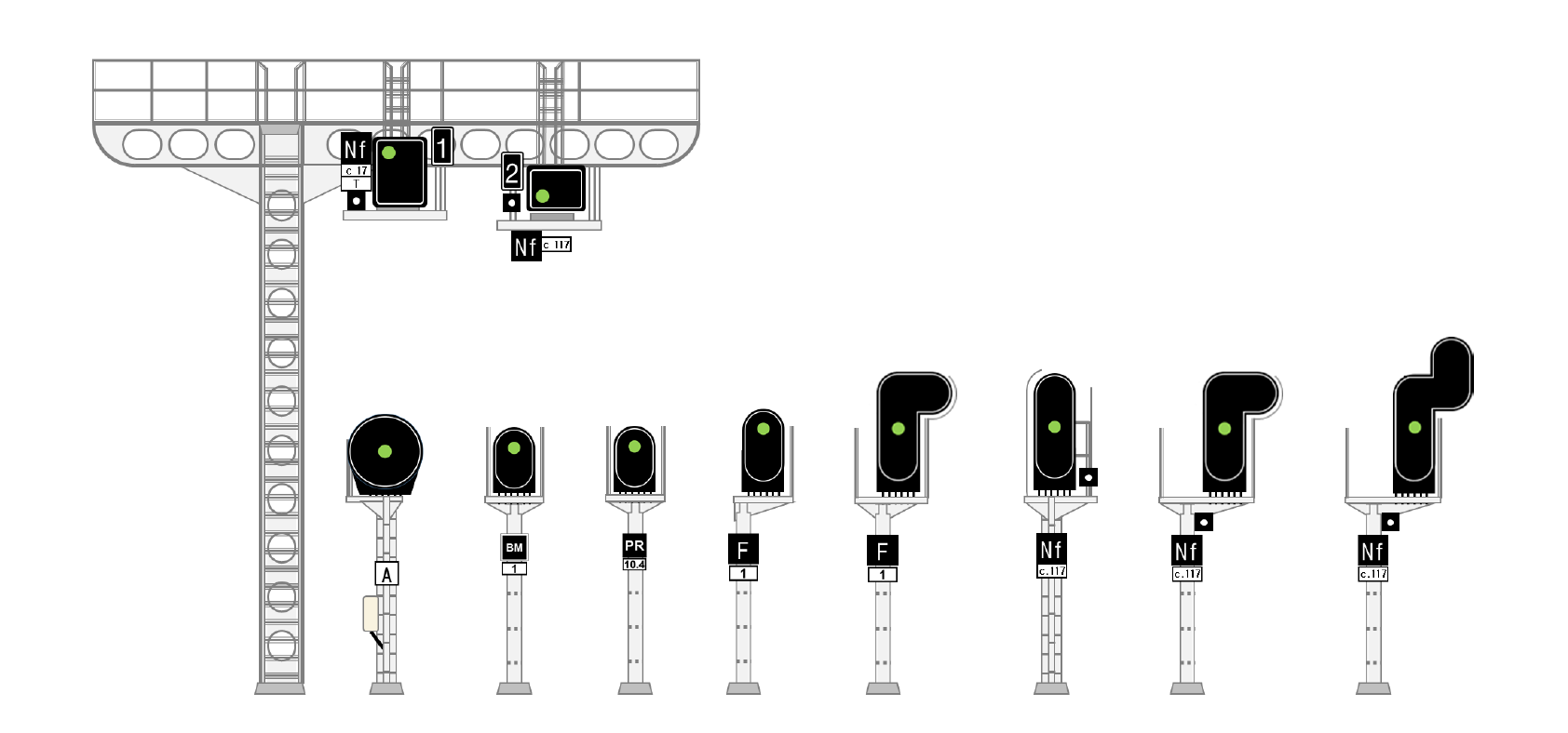
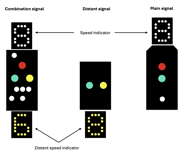
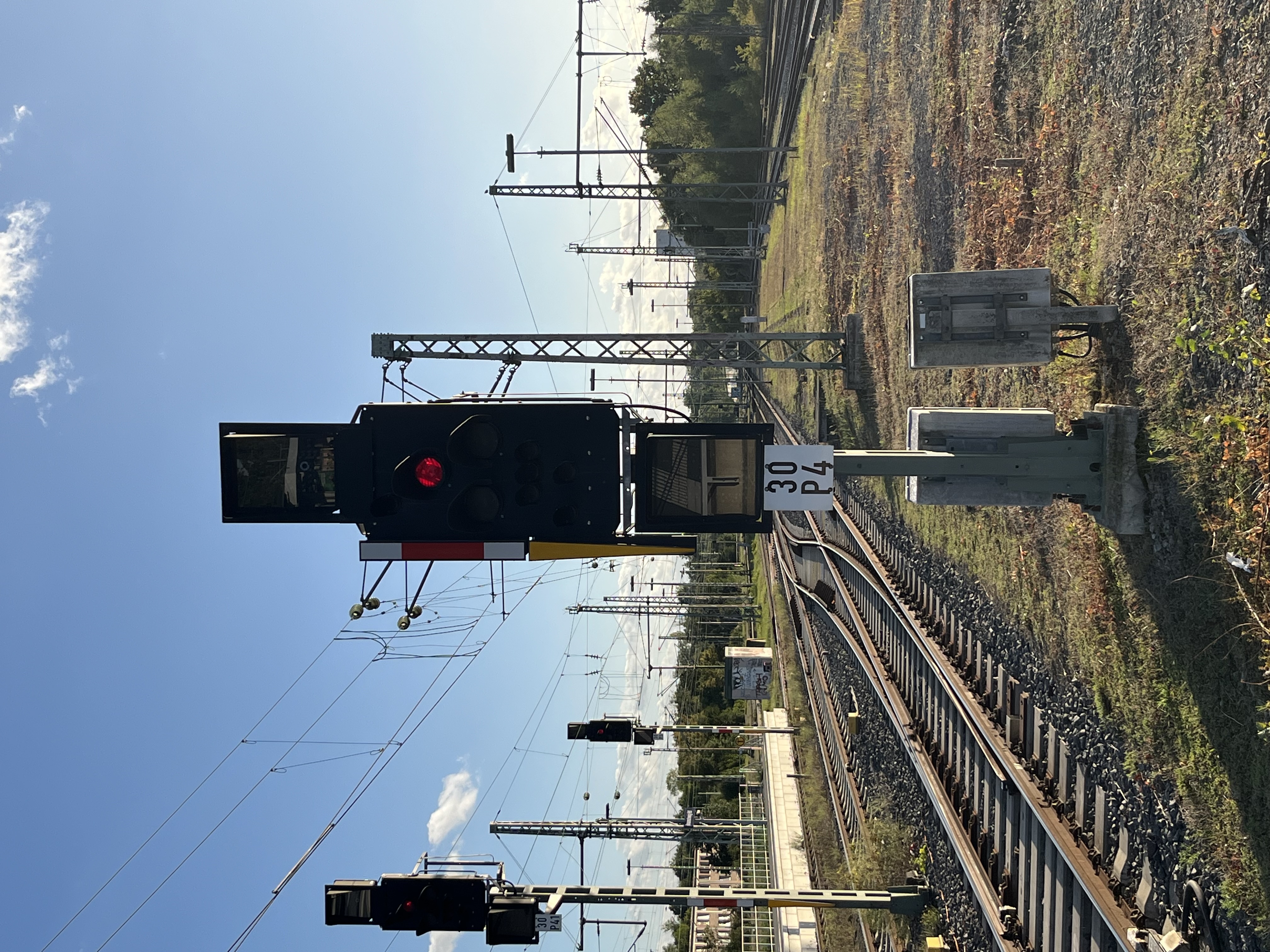
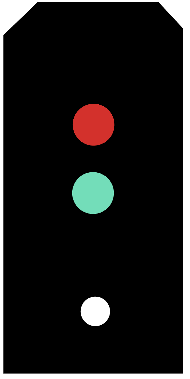
Appearance of Ks-Signals with speed indicators
Ks-signal in Braunschweig main station, Source: Dominik Wefering
Signal Indications on a Ks-Signal
Description
Aspect
Meaning
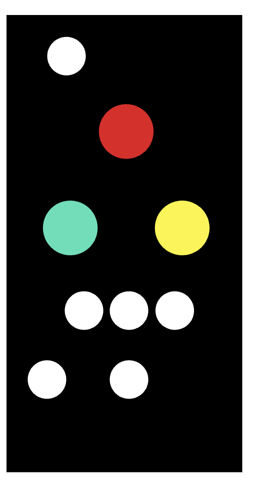
Combination signal
combination signals have the function of both main signal and distant signal
main signal
main signals indicate whether the track section ahead may be run over
distant signal
Distant signals indicate which signal aspect is to be expected at the corresponding next main signal.These are positioned at the braking distance from the next main signal
Stop (Hp 0)
the signal prohibits the passing of a train
Clear (Ks 1)
1. The signal permits the passing at the maximum speed allowed on the section, unless a speed restriction is indicated by a speed indicator.2. The green luminous spot blinks if a distant speed indicator shows in the signal, indicating a speed restriction at the next main signal
Expect Stop (Ks 2)
the signal permits the passing and indicates a stop at the next main signal
The Ks system includes specific indicators to communicate speed restrictions to train drivers.
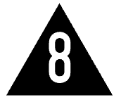
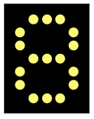
Speed Indicator (Zs 3)
The speed displayed by the Zs 3 indicator defines the maximum permissible speed from the signal onward, specifically within the subsequent switch area.
The numeric value shown on the indicator represents the allowed speed in kilometers per hour, calculated as 10 times the displayed number.
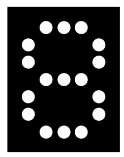
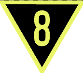
Distant Speed Indicator (Zs 3v)
means: expect speed indicator Zs 3
The Zs 3v indicator provides advance notice of a speed restriction at the next main signal.
Similar to the Zs 3 indicator, the displayed number corresponds to a permissible speed of 10 times the value in km/h at the upcoming main signal.
The Linienförmige Zugbeeinflussung (LZB) is a continuous automatic train control system used to ensure safe and efficient operation at high speeds. Unlike the Punktförmige Zugbeeinflussung (PZB) (see PZB), which transmits discrete signal information at fixed track points, the LZB enables continuous bi-directional data exchange between the train and the trackside control center. This allows for real-time supervision of speed and position and forms the basis for cabin signalling at speeds exceeding 160 km/h.
System Structure
The LZB consists of three main components (DB, 2019):
Trackside Equipment The track contains cable loops laid between the rails, divided into multiple segments. These loops enable continuous communication between the train and the LZB control center.
Source: Pachl (2022)
Train Equipment Each LZB-equipped vehicle has an onboard unit that:
continuously determines the train’s position,
receives and interprets control information from the LZB center,
calculates braking curves and speed supervision data,
and automatically applies braking if limits are exceeded.
LZB Control Center The control center transmits Movement Authorities (MAs) to the trains within the controlled area, defining:
the permissible target distance,
the permitted speed at each section,
and other route-specific properties like gradients
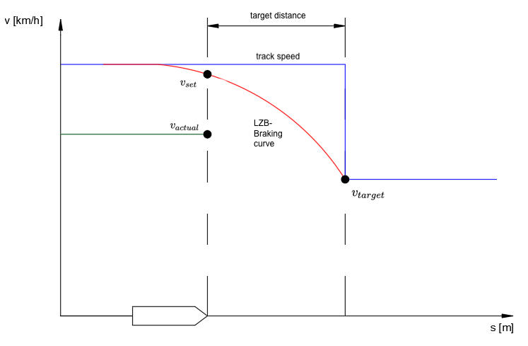
Functionality
During operation, the train continuously reports its position to the LZB center. In return, it receives updated target data like setpoint speed (\(v_{set}\)), target speed (\(v_{target}\)) and target distance.
based on: Pachl (2022)
The onboard unit calculates braking curves for different supervision thresholds:
Permitted Speed Curve – permissible maximum speed at each position. This is the curve the driver train should follow.
Warning Curve - gives an acoustic warning to the driver when the permitted speed curve is exceeded by 5 km/h.
Emergency Brake Curve – triggers an emergency brake if the train fails to decelerate sufficiently.
The braking curve that is set by the onboard unit is based on:
maximum track speed
slope¹
braking percentage of the train
The next target point is displayed up to 10.000 m in front of the train. The speed limit equals the maximum track speed or the maximum possible speed of the train itself. (Murr, 1991)
Braking Curves
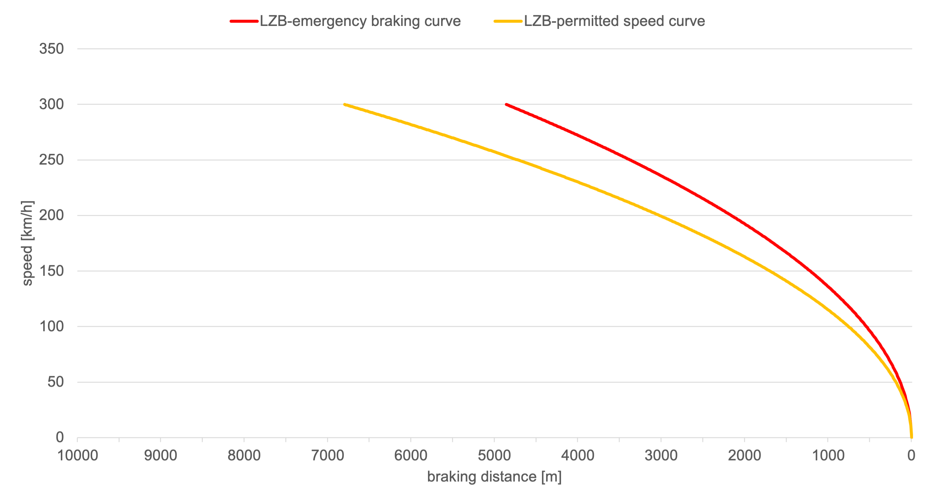
For LZB there exist twelve braking curves with values between 0,115 und 1,10 m/s². The value of the emergency braking curve is about 40% higher than the permitted speed curve.
The deceleration of the individual braking curves remains constant across the entire speed range.
Braking Curve Nr (BRN)
A
B
1
2
3
4
5
6
7
8
9
10
Emergency Braking Curve [m/s²]
0,115
0,2
0,29
0,375
0,460
0,545
0,63
0,715
0,8
0,9
1,0
1,1
Permitted Speed Curve [m/s²]
0,08
0,14
0,21
0,27
0,33
0,39
0,45
0,51
0,57
0,64
0,71
0,79
based on: Braun (1988)
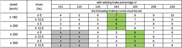
The illustration below shows the braking curves for BRN 6 as an example.
The train driver enters the permissible speed and the brake percentage into the vehicle device. The gradient is specified for the route. The LZB uses this data to set the necessary braking curve. (Braun, 1988)
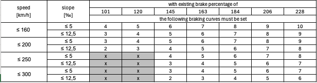
For Passenger trains the following curves must be set:
based on: Braun (1988)
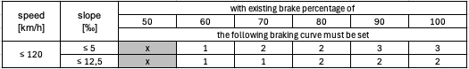
For freight trains the following curves must be set:
based on: Braun (1991)
Where an “x” is written the combination of braking percentage and speed must not be possible.
Full Block and Partial Block Mode
The LZB can operate in two different control modes: Full Block Mode (german: Ganzblockmodus) and Partial Block Mode (german: Teilblockmodus). Both modes determine how the track is divided into supervised sections and how the control center grants Movement Authorities (MAs) to trains.
In Full Block Mode, each train occupies an entire block section, similar to traditional fixed-block signalling systems. A new train is only allowed to enter a block once the preceding train has completely cleared it. This mode ensures maximum safety but limits the line capacity. (Pachl, 2022)
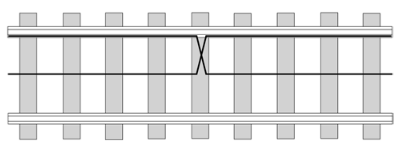
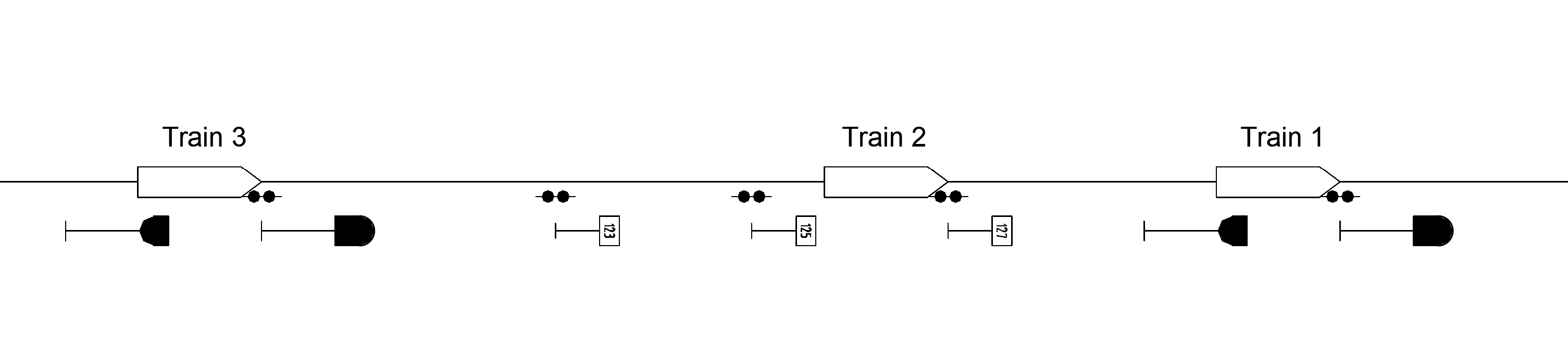
In Partial Block Mode, the LZB subdivides a block into several smaller LZB subsections. Each subsection can be individually monitored and released as the train progresses, allowing the following train to enter the same block earlier. This dynamic release mechanism increases line capacity significantly while maintaining safe separation between trains. (Pachl, 2022) The partial block principle thus enables higher traffic density and shorter headways, which are especially important for high-speed or high-frequency railway operations. The typical length of a LZB subsection is about 1200 m (Busse, 2021)
The picture below shows the Partial Block Mode. Train 1 occupies the block between the two main signals. Train 2 is a LZB train and is therefore allowed to enter the block until the section marker. Train 3 is not equipped with LZB and is therefore not allowed to enter the occupied block.
OSRD-modeling
Braking curve is based on the permitted speed curve.
Warning curve and emergency braking curve are not modeled.
The braking curve is constant over the whole braking distance.
The constant deceleration is used for braking to a full stop, for speed changes and for the spacing and routing requirements.
For Partial Block Mode, LZB section markers are placed at the entry of LZB subsections.
Switches are released when the following detector is crossed.
There are no overlaps implemented yet (only affects blocking time).
Simplifications and Assumptions
All LZB-trains have a sight distance of 10.000 m (impacts the distance for average slope calculation, and maybe future work on dynamic simulation).
The slope used to choose the braking curve is the average slope calculated within these 10.000 m.
The train follows the permitted speed curve and does not brake earlier.
OSRD trains do not have brake percentage values, so an alternative to define the used braking curves was used:
The braking curves are picked depending on the rolling stock category, the train’s maximum speed and the average slope (exact modeling and code to be determined).
Determination of the braking curve
The average deceleration of each speed category was calculated and the corresponding braking curves were chosen. The resulting curves are also the ones that are used the most.
The resulting curves for ≤ 200 and ≤ 250 km/h were the same so they were put together in one category
This results in the following braking curves that must be set for passenger trains:
Slope [‰]
≤ 160 km/h
160 - 250 km/h
250 - 300 km/h
≤ 5
7
6
5
≤ 12,5
6
5
4
The corresponding deceleration (permitted speed curve) values that must be set for passenger trains depending on the maximum train speed and slope are as follows:
Slope [‰]
≤ 160 km/h
160 - 250 km/h
250 - 300 km/h
≤ 5
0,57
0,51
0,45
≤ 12,5
0,51
0,45
0,39
possible further simplification for OSRD: deceleration in other LZB-modeling tools is 0,5 for all passenger trains
For freight trains only two decelerations (permitted speed curve) were chosen. They cover all the relevant cases for freight trains with LZB.
Slope [‰]
≤ 120 km/h
≤ 5
0,33
≤ 12,5
0,27
possible further simplification for OSRD: deceleration in other LZB-modeling tools is 0,3 for all freight trains
References
Alfred Braun. „Aufstellen von Bremstafeln für Strecken mit Linienzugbeeinflussung“. In: ZEV Glasers Annalen 4 (1988), S. 108–118.
Alfred Braun. “Die LZB-Bremstafeln für Güterzüge”. In: Eisenbahningenieurkalender (1991), S. 275-282
DB AG. Ril 819.1320 LZB; Grundsätze für die Ausrüstung mit linienförmiger Zugbeeinflussung. Dez. 2019.
Eduard Murr. „Systembeschreibung der Linienzugbeeinflussung (LZB) der Deutschen Bundesbahn“. In: Eisenbahningenieurkalender (1991), S. 285–317.
Jörn Pachl. Systemtechnik des Schienenverkehrs: Bahnbetrieb planen, steuern und sichern. de. Wiesbaden: Springer Fachmedien Wiesbaden, 2022.
Matthias Busse. „Der optimierte Einsatz von ETCS-Bremskurven“. Dissertation. Dresden: Technische Universität Dresden, Feb. 2021.
¹ The slope is saved in the LZB-Control Center. We don’t yet have reliable information on how the slope in front of the train is calculated, when determining the braking curve.
4.3.2 - Punktförmige Zugbeeinflussung (PZB)
Overview
The Punktförmige Zugbeeinflussung (PZB) is an intermittent train protection system used on most conventional railway lines in Germany. Its primary function is to ensure that trains respond correctly to restrictive signal aspects and speed limits. The PZB monitors the train’s compliance with braking requirements and automatically initiates braking interventions when these are violated.
The system acts as a safeguard against driver inattention or failure to observe signals and thereby prevents trains from passing stop signals or exceeding permitted speeds (DB, 2014).
The core tasks consist of monitoring braking maneuvers, protecting against trains continuing past stop signals, and preventing trains from moving forward against stop signals, for example after a scheduled stop at platform (DB, 2024).
System Components
The PZB consists of two main parts:
Trackside equipment, composed of inductive magnets installed along the track near signals.
Onboard equipment, located on the locomotive to communicate with the magnets and supervise train operation.
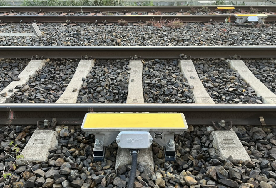
Trackside Magnets
Source: Dominik Wefering
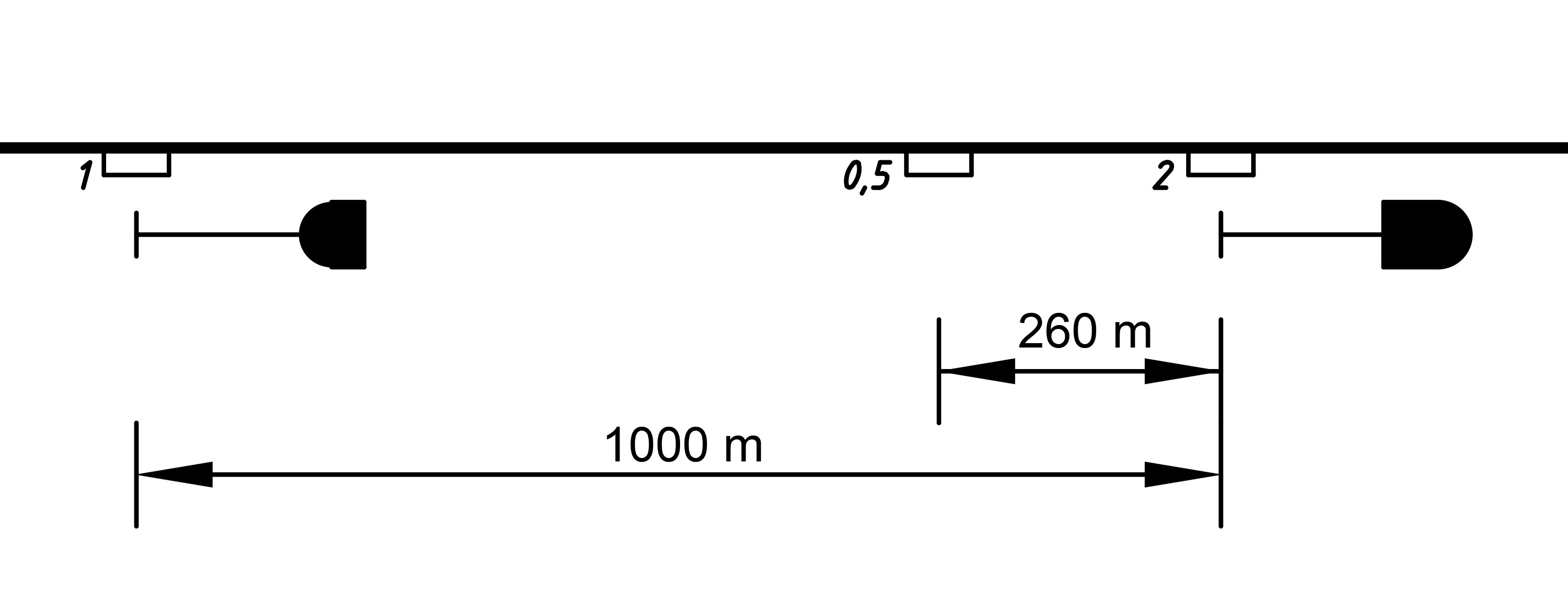
Three types of track magnets are used, each operating at a distinct frequency (DB, 2014):
Frequency
Location
Function
1000 Hz
At the distant signal
Activates supervision when the distant signal shows a restrictive aspect (Ks 2). The driver must acknowledge the magnet within 2,5 seconds and a braking sequence begins.
500 Hz
About 260 m before the main signal
Reinforces braking supervision before a stop signal. The train must reduce its speed further.
2000 Hz
At the main signal
Immediately triggers an emergency brake if the train passes a stop signal (Hp 0).
On combination signals (see Ks Signalling) there are double-track magnets with frequencies of 1000 and 2000 Hz combined.
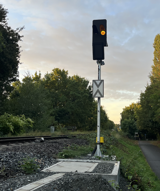
The picture below shows an distant signal with the aspect Ks 2 and the 1000 Hz magnet to the left of the signal.
Source: Dominik Wefering
Onboard Equipment
The onboard system receives inductive signals from the track magnets and monitors (DB, 2014):
The acknowledgement of signal aspects by the driver.
The elapsed time and distance since the last magnet activation.
The train speed relative to permitted limits defined by the current supervision state.
If the driver fails to acknowledge or reduce speed as required, the system triggers an automatic emergency brake until a full stop.
Train types
PZB makes a distinction between three train types (german: Zugart): O, M, U
O = Upper train type (german: Obere Zugart)
M = Middle train type (german: Mittlere Zugart)
U = Lower train type (german: Untere Zugart)
The distinction is based on the brake percentages of the train (Maschek, 2022):
Train type
Brake percentages
monitored maximum speed
O
> 110
165
M
66 - 110
125
U
< 66
105
The braking percentage is a standardized measure in railway operations used to quantify a train’s braking capability. It is defined as the ratio of the effective braking weight (B) to the train mass (m), multiplied by 100 (Kache, 2024):
$$ \lambda=\frac{B}{m}*100 $$
This value indicates how effectively a train can decelerate relative to its mass. A higher braking percentage corresponds to a shorter braking distance, allowing for a direct comparison between different trains.
Supervision Logic of PZB
The system evaluates train movement against predefined supervision limits. Each magnet initiates a specific monitoring function:
Time-based supervision
Distance-based supervision
Speed thresholds
These parameters are dynamically managed depending on the train type.
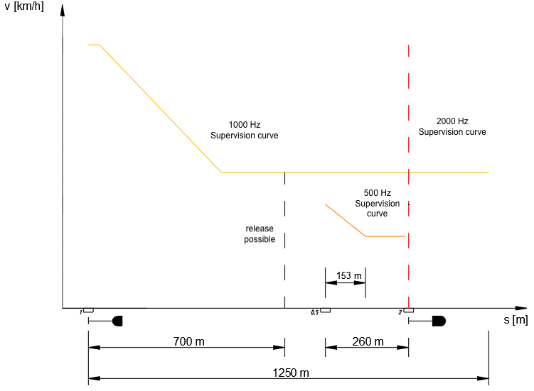
Basic principle of PZB supervision
The basic principle of the supervision curves in PZB is shown in the following illustration (see following schema for the exact shape of decrease):
based on Maschek (2022)
Supervision Curves
The supervised values depending on the train type are as follows:
Train type
Upper (O)
Middle (M)
Lower (U)
Maximum Speed
165 km/h
125 km/h
105 km/h
Braking curve of 1000 Hz influence
85 km/h after 23 Sec.
70 km/h after 29 Sec.
55 km/h after 35 Sec.
Braking curve of 500 Hz influence
from 65 to 45 km/h within 153 m
from 50 to 35 km/h within 153 m
from 40 to 25 km/h within 153 m
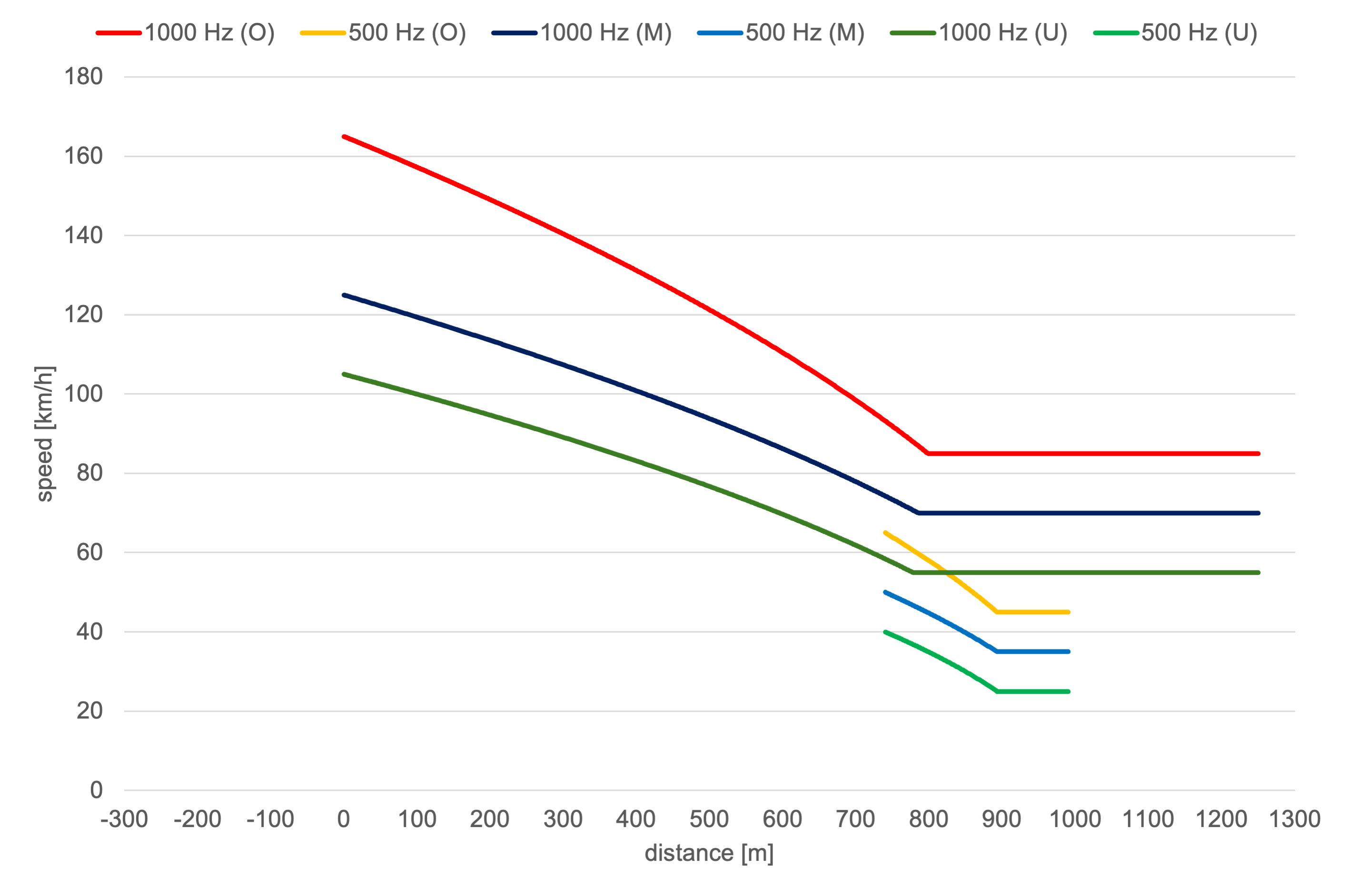
The values in the table above result in the following six supervision curves for the PZB for each train type:
Release from 1000 Hz supervision
700 m after the 1000 Hz influence, the train driver can stop braking if the main signal has turned back to Ks 1 in the meantime. In this case, he can accelerate again to the maximum permitted speed.
Restrictive Mode
If a train stops while a PZB supervision is active, or if its speed drops below the switching speed of 10 km/h for at least 15 seconds, more restrictive supervision curves are activated.
In this restrictive mode, the 1000 Hz supervision curve is lowered to a maximum permissible speed of 45 km/h. Similarly, for the 500 Hz supervision, the system enters a restrictive state if, within the 153 m monitoring section, the train travels for more than 15 seconds below the switching speed of 30 km/h, while the speed continues to decrease toward 10 km/h.
Typical example: When a train stops at the platform, the overlap behind the destination signal is cleared and the switches are released. The restrictive curves ensure that if the train starts moving without permission after stopping, it will travel slowly enough so as not to pose a danger to other trains. Once it arrives at the 2000 Hz magnet, its speed will be low enough for the emergency brake to make it come to a full stop wihtin the overlap.
Safety Function
The PZB ensures safety through automatic emergency braking when:
The driver fails to acknowledge a restrictive signal,
The train exceeds the monitored speed during supervision,
Or a stop signal (Hp0) is passed.
This guarantees that even under human error or distraction, train operations remain within safe limits and the risk of signal overruns is minimized.
OSRD-modeling
The supervision curves are only used for calculating the deceleration values. They are not modeled in OSRD.
Emergency braking is not modeled and restrictive mode is not modeled.
The PZB braking curve is modeled for each train type with two constant decelerations \(a_{type,1}\) and \(a_{type,0,5}\).
The deceleration is used for braking to a full stop, for slowdowns and for spacing and routing requirements.
\(a_{type,1}\) corresponds to a deceleration that brakes the train from the maximum speed applicable to the train type \(v_{type,max}\) down to below the check speed of the 500 Hz condition \(v_{type,check,0,5}\) (1000 Hz phase).
\(a_{type,0,5}\) corresponds to a deceleration that brakes the train from the speed below the check speed \(v_{type,res,0,5}\) to a full stop within the distance between the 500 Hz Magnet and the associated main signal (500 Hz phase).
There are no overlaps implemented yet (only affects blocking time).
As PZB trains can use LZB tracks, in addition to LZB signal data should provide PZB signal at the entry of the LZB block and not at the entry of LZB subsections (It is only used for LZB partial block mode).
Simplifications and assumptions
There is no infrastructure model for magnets in OSRD. The modeling is therefore based on signal locations.
A constant distance of \(s_{0,5}\) = 260 m is assumed as fictitious trigger of the 500 Hz phase.
A distant signal spacing of \(s_{distant}\) = 1000 m is assumed.
A sighting distance for distant signal of \(s_{sight}\) = 300 m is assumed.
OSRD trains do not have brake percentage values, so an alternative to define the used braking curves was used:
The braking curves are set depending on the rolling stock category and the train’s maximum speed.
Upper Train type: Passenger Train with \(v_{O,max}\) = 165 km/h,
Middle Train type: Freight or Passenger Train with \(v_{M,max}\) = 125 km/h,
Lower Train type: Freight train with \(v_{U,max}\) = 105 km/h.
Calculating the deceleration values
At first we have to calculate the deceleration for the 1000 Hz Phase, which was done with:
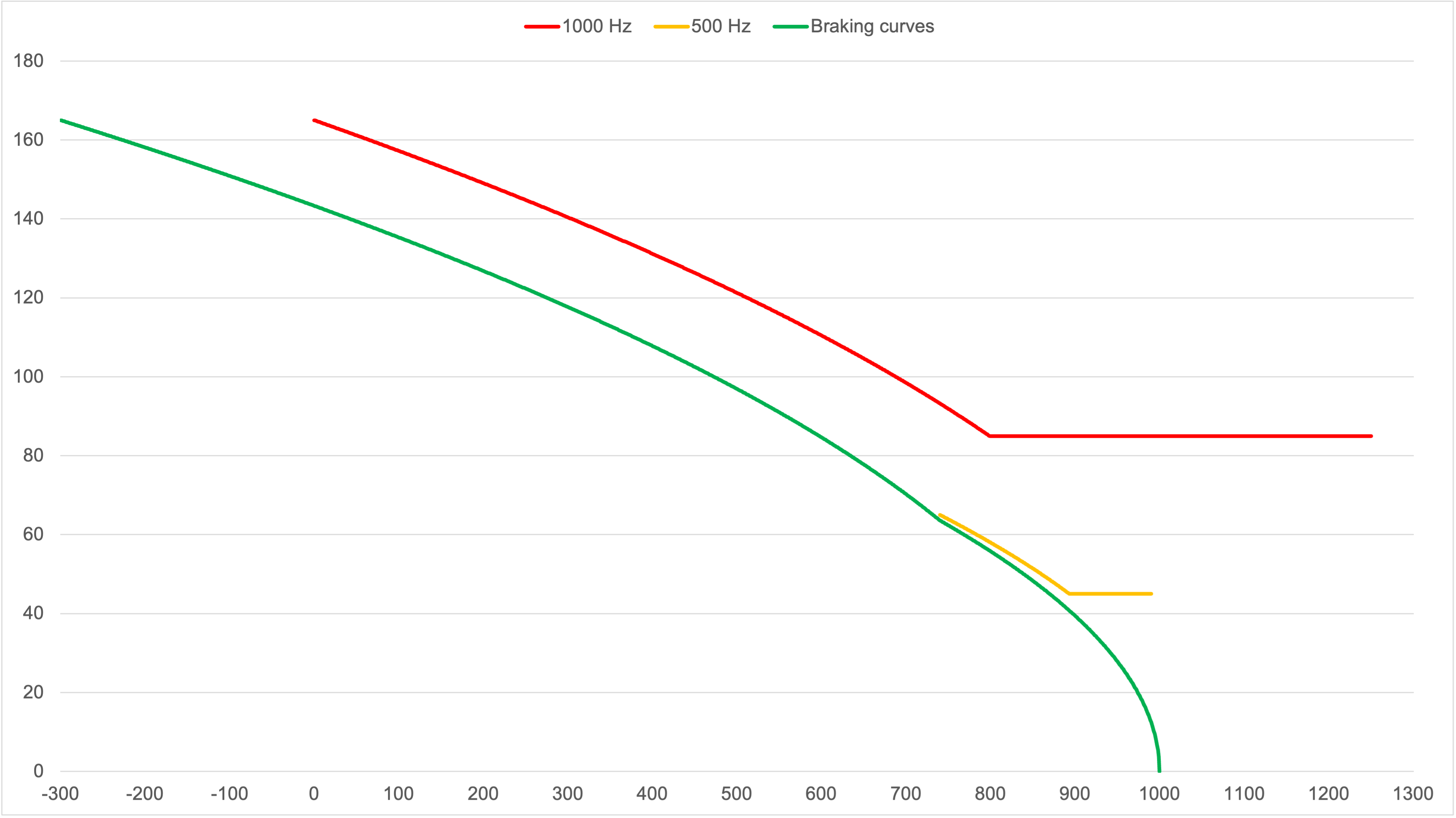
The resulting braking curves for each train type are as follows:
The 1000 Hz and 500 Hz curves are displayed for informational purpose only.
Upper train type (O)
\(a_{O,1}\) = 0,86 m/s² for the 1000 Hz phase and
\(a_{O,0,5}\) = 0,6 m/s² for the 500 Hz phase.
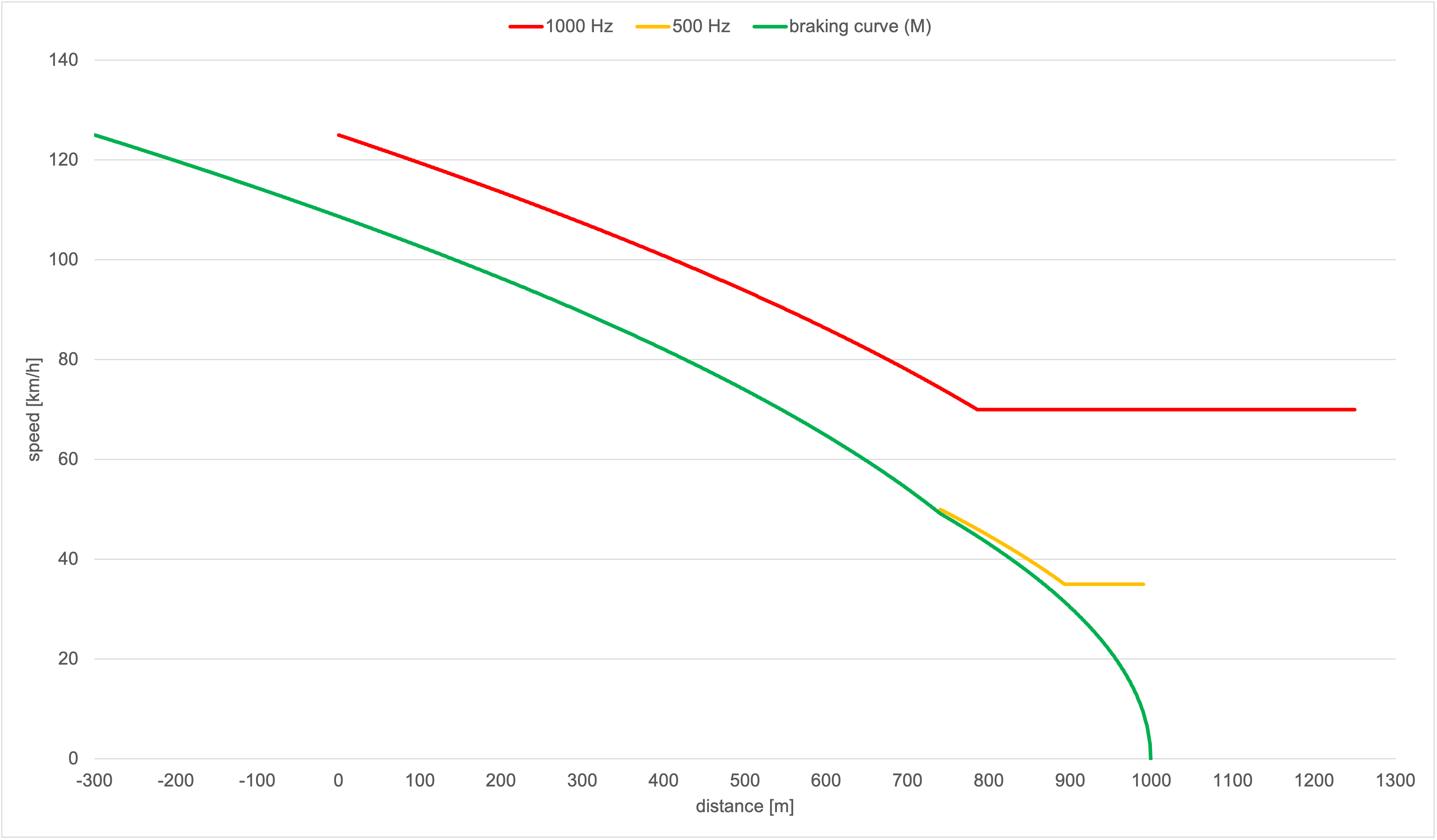
Middle train type (M)
\(a_{M,1}\) = 0,49 m/s² for the 1000 Hz phase and
\(a_{M,0,5}\) = 0,36 m/s² for the 500 Hz phase.
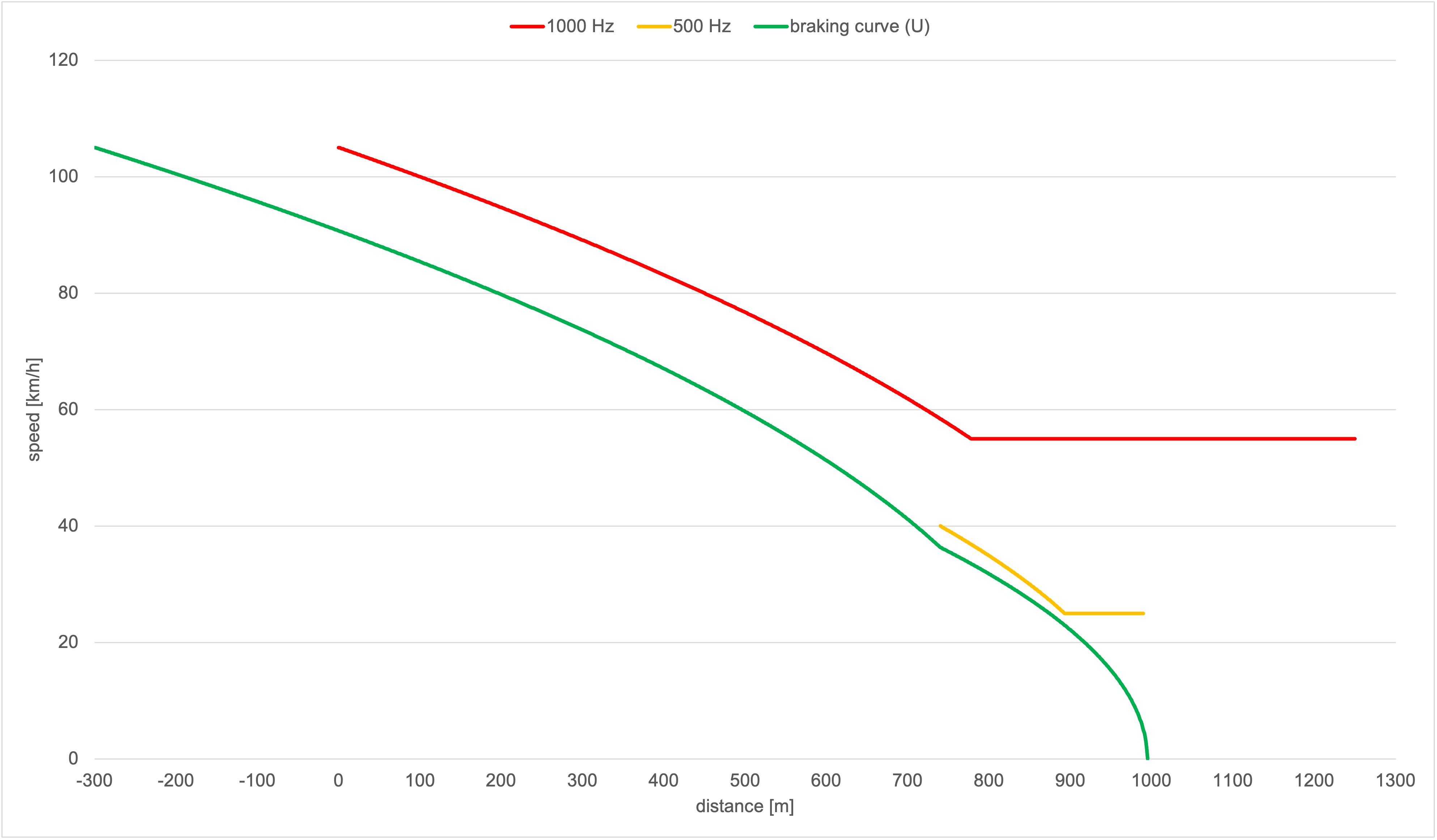
Lower train type (U)
\(a_{U,1}\) = 0,36 m/s² for the 1000 Hz phase and
\(a_{U,0,5}\) = 0,2 m/s² for the 500 Hz phase.
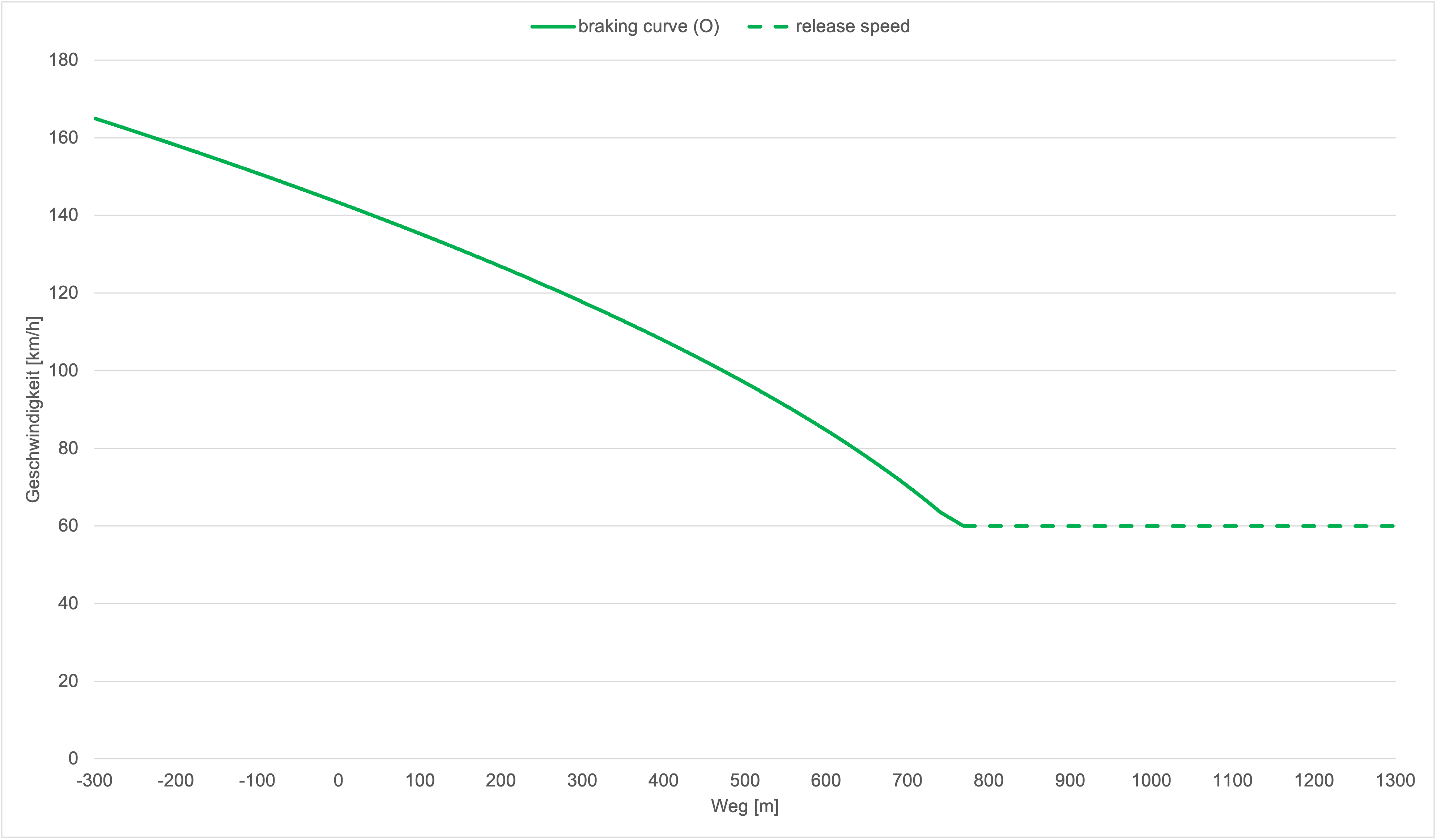
Slowdown braking curve
In lineside signalling like the Ks Signalling the speed restrictions generally apply at the next main signal. Therefore the slowdown needs to be handled differently, otherwise a train could harm the PZB conditions if the braking curve is applied to the destination point with the speed restriction.
For slowdowns there are two cases:
The target speed is equal or higher than the initial checked speed of the 500 Hz magnet: The train brakes directly to the destination with the constant deceleration of \(a_{type,1}\). This allows to save some capacity, since the train is able to brake later.
The target speed is below the initial checked speed of the 500 Hz magnet: The train follows the stop braking curve until it reaches the target speed and then the train continues in a steady-state running at the target speed (release speed).
References
DB AG. Ril 483.0111 Punktförmige Zugbeeinflussunganlagen bedienen. Aug. 2014
DB AG. Ril 819.1310 Punktförmige Zugbeeinflussung (PZB); Grundsätze für das Ausrüsten von Strecken. Juli 2024.
Martin Kache. Fahrdynamik der Schienenfahrzeuge: Grundlagen der Leistungsauslegung sowie der Energiebedarfs- und Fahrzeitberechnung. de. Wiesbaden: Springer Fachmedien Wiesbaden, 2024
Ulrich Maschek. Sicherung des Schienenverkehrs: Grundlagen und Planung der Leit- und Sicherungstechnik. de. Wiesbaden: Springer Fachmedien Wiesbaden, 2022.