This is the multi-page printable view of this section. Click here to print.
Models
1 - Infrastructure example
Introduction
This page gives an example of how the data formats are used to describe an infrastructure in OSRD.
For this purpose, let’s take as an example the following toy infrastructure:

Tip
To zoom in on diagrams, click on the edit button that appears when hovering over it.This diagram is an overview of the infrastructure with lines and stations only.
This infrastructure is not meant to be realistic, but rather meant to help illustrate OSRD’s data model. This example will be created step by step and explained along the way.
The infrastructure generator
In the OSRD repository is a python library designed to help generate infrastructures in a format understood by OSRD.
The infrastructure discussed in this section can be generated thanks to small_infra.py file. To learn more about the generation scripts, you can check out the related README.
Tracks
Track sections
The first objects we need to define are TrackSections. Most other objects are positioned relative to track sections.
A track section is a section of rail (switches not included). One can chose to divide the tracks of their infrastructure in as many track sections as they like. Here we chose to use the longest track sections possible, which means that between two switches there is always a single track section.
Track sections is what simulated trains roll onto. They are the abstract equivalent to physical rail sections. Track sections are bidirectional.
In this example, we define two tracks for the line between the West and North-East stations. We also have overpassing tracks at the North and Mid-West stations for added realism. Finally, we have three separate tracks in the West station, since it’s a major hub in our imaginary infrastructure.

Important
TrackSections are represented as arrows in this diagram to stress the fact that they have a start and an end. It matters as objects positioned on track sections are located using their distance from the start of their track section.
Therefore, to locate an object at the beginning of its track section, set its offset to 0. To move it to the end of its track section, set its offset to the length of the track section.
These attributes are required for the track section to be complete:
length: the length of the track section in meters.geo: the coordinates in real life (geo is for geographic), in the GeoJSON format.- cosmetic attributes:
line_name,track_name,track_numberwhich are used to indicate the name and labels that were given to the tracks / lines in real life.
For all track sections in our infrastructure, the geo attributes very much resemble the given diagram.
For most track sections, their length is proportional to what can be seen in the diagram. To preserve readability, exceptions were made for TA6, TA7, TD0 and TD1 (which are 10km and 25km).
Node
A Node represents a node in the infrastructure. In an OSRD simulation, a train can only move from one section of track to another if they are linked by a node.
Node Types
NodeTypes have two mandatory attributes:
ports: A list of port names. A port is an endpoint connected to a track section.groups: A mapping between group names and lists of branch (connection between 2 ports) that characterises the different possible positions of the node type
At any time, all nodes have an active group, and may have an active branch, which always belongs to the active group. During a simulation, changing the active branch inside a group is instantaneous, but changing the active branch across groups (changing the active group) takes configurable time.
This is because a node is a physical object, and changing active branch can involve moving parts of it. Groups are designed to represent the different positions that a node can have. Each group contains the branches that can be used in the associated node position.
The duration needed to change group is stored inside the Node, since it can vary depending on the physical implementation of the node.
Our examples currently use five node types. Node types are just like other objects, and can easily be added as needed using extended_switch_type.
1) Link
This one represents the link between two sections of track. It has two ports: A and B.

It is used in the OSRD model to create a link between two track sections. This is not a physical object.
2) The Point Switch
The ubiquitous Y switch, which can be thought of as either two tracks merging, or one track splitting.
This node type has three ports: A, B1 and B2.

There are two groups, each with one connection in their list: A_B1, which connects A to B1, and A_B2 which connects A to B2.
Thus, at any given moment (except when the switch moves from one group to another), a train can go from A to B1 or from A to B2 but never to both at the same time. A train cannot go from B1 to B2.
A Point Switch only has two positions:
- A to B1
- A to B2


3) The Crossing
This is simply two tracks crossing each other.
This type has four ports: A1, B1, A2 et B2.

It has only one group containing two connections: A1 to B1 and A2 to B2. Indeed this kind of switch is passive: it has no moving parts. Despite having a single group, it is still used by the simulation to enforce route reservations.
Here are the two different connections this switch type has:
- A1 to B1
- A2 to B2


4) The Double slip switch
This one is more like two point switches back to back. It has four ports: A1, A2, B1 and B2.

However, it has four groups, each with one connection. The four groups are represented in the following diagram:
- A1 to B1
- A1 to B2
- A2 to B1
- A2 to B2


5) The Single slip switch
This one looks more like a cross between a single needle and a crossover. It has four ports: A1, A2, B1 and B2.

Here are the three connections that can be made by this switch:
- A1 to B1
- A1 to B2
- A2 to B2


Back to nodes
A Node has three attributes:
node_type: the identifier of theNodeTypeof this node.ports: a mapping from port names to track sections extremities.group_change_delay: the time it takes to change which group of the node is activated.
The port names must match the ports of the node type chosen. The track section endpoints can be start or end, be careful to chose the appropriate ones.
Most of our example’s nodes are regular point switches. The path from North station to South station has two cross switches. Finally, there is a double cross switch right before the main line splits into the North-East and South-East lines.

It is important to note that these node types are hard-coded into the project code. Only the extended_node_type added by the user will appear in the railjson.
Curves and slopes
Curves and Slopes are instrumental to realistic simulations. These objects are defined as a range between a begin and end offsets of one track section. If a curve / slope spans more than one track section, it has to be added to all of them.
The slope / curve values are constant on their entire range. For varying curves / slopes, one needs to create several objects.
Slope values are measured in meters per kilometers, and the curve values are measured in meters (the radius of the curve).
begin value should always be smaller than the end value. That is why the curve / slope values can be negative: an uphill slope of 1 going from offset 10 to 0 is the same as a downhill slope of -1 going from offsets 0 to 10.In the small_infra.py file, we have slopes on the track sections TA6, TA7, TD0 and TD1.
There are curves as well, on the track sections TE0, TE1, TE3 and TF1.
Interlocking
All objects so far contributed to track topology (shape). Topology would be enough for trains to navigate the network, but not enough to do so safely. To ensure safety, two systems collaborate:
- Interlocking ensures trains are allowed to move forward
- Signaling is the mean by which interlocking communicates with the train
Detectors
These objects are used to create TVD sections (Track Vacancy Detection section): the track area in between detectors is a TVD section. When a train runs into a detector, the section it is entering becomes occupied. The only function of TVD sections is to locate trains.
In real life, detectors can be axle counters or track circuits for example.
For this mean of location to be efficient, detectors need to be placed regularly along your tracks, not too many because of cost, but not too few, because then TVD sections would be very large and trains would need to be very far apart to be told apart, which reduces capacity.
There often are detectors close to all sides of switches. This way, interlocking is made aware pretty much immediately when a switch is cleared, which is then free to be used again.
In OSRD, detectors are point objects, so all the attributes it needs are its id, and track location (track and offset).

Some notes:
- Between some points, we added only one detector (and not two), because they were really close together, and it would have made no sense to create a tiny TVDS between the two. This situation happened on track sections (TA3, TA4, TA5, TF0 and TG3).
- In our infrastructure, there are relatively few track sections which are long enough to require more detectors than just those related to switches. Namely, TA6, TA7, TDO, TD1, TF1, TG1 and TH1. For example TD0, which measures 25km, has in fact 17 detectors in total.
Buffer stops
BufferStops are obstacles designed to prevent trains from sliding off dead ends.
In our infrastructure, there is a buffer stop on each track section which has a loose end. There are therefore 8 buffer stops in total.
Together with detectors, they set the boundaries of TVD sections (see Detectors)
Routes
A Route is an itinerary in the infrastructure. A train path is a sequence of routes. Routes are used to reserve section of path with the interlocking. See the dedicated documentation.
It is represented with the following attributes:
entry_pointandexit_point: references detectors or buffer stops which mark the beginning and the end of the Route.entry_point_direction: Direction on a track section to start the route from theentry_point.switches_direction: A set of directions to follow when we encounter a switch on our Route, to build this Route fromentry_pointtoexit_point.release_detectors: When a train clears a release detector, resources reserved from the beginning of the route until this detector are released.
Signaling
Thanks to interlocking, trains are located and allowed to move. It’s a good start, but meaningless until trains are made aware of it. This is where Signals come into play: signals react to interlocking, and can be seen by trains.
How trains react to signals depends on the aspect, kind of signal, and signaling system.
Here are the most important attributes for signals:
linked_detector: The linked detector.type_code: The type of signal.direction: The direction it protects, which can simply be interpreted as the way in which it can be seen by an incoming train (since there are lights only on one side…). Direction is relative to track section orientation.- Cosmetic attributes like
angle_geoorsidewhich control the way in which the signals are displayed in the front-end.
Here is a visualization of how one can represent a signal, and which direction it protects.

The way the signals are arranged is highly dependent on both signaling system and infrastructure manager.
Here are the basic rules used for this example infrastructure:
- We add two spacing signals (one per direction) for each detector that is cutting a long TVD section into smaller ones.
- Switch entries where a train might have to stop are protected by a signal (which is located outside of the switch TVD section). It must be visible from the direction used to approach the switch. When there are multiple switches in a row, only the first one usually needs protection, as interlocking is usually designed as not to encourage trains stopping in the middle of intersections.
Note that detectors linked to at least one signal are not represented, as there are not signals without associated detectors in this example.
To get the id of a detector linked to a signal, take the signal’s id and replace S by D (e.g. SA0 -> DA0).

Electrification
To allow electric trains to run on our infrastructure, we need to specify which parts of the infrastructure is electrified.
Catenaries
Catenaries are objects that represent the overhead wires that power electric trains. They are represented with the following attributes:
voltage: A string representing the type of power supply used for electrificationtrack_ranges: A list of range of track sections (TrackRanges) covered by this catenary. ATrackRangeis composed of a track section id, abeginoffset and anendoffset.
In our example infrastructure, we have two Catenaries:
- One with
voltageset to"1500", which covers only TA0. - One with
voltageset to"25000", which covers all others except TD1.
This means that only thermal trains can cross the TD1 track section.
Our example also outlines that, unlike its real life counterpart, a single Catenary may cover the whole infrastructure.
Neutral Sections
In some parts of an infrastructure, the train drivers may be instructed - mainly for safety reasons - to cut the power supply to the train.
To represent such parts, we use NeutralSections. They are represented mainly with the following attributes:
track_ranges: A list ofDirectedTrackRanges(track ranges associated to a direction) which are covered by this neutral section.lower_pantograph: A boolean indicating whether the train’s pantograph should be lowered while in this section.
In our example infrastructure, we have three NeutralSections: one at the junction of the "1500" and "25000" catenaries, one on TA6 and one on TG1 and TG4.
For more details about the model see the dedicated page.
Miscellaneous
Operational points
Operational point is also known in French as “Point Remarquable” (PR).
One OperationalPoint is a collection of points (OperationalPointParts) of interest.
For example, it may be convenient (reference point for train operation) to store the location of platforms as parts and group them by station in operational points.
In the same way, a bridge over tracks will be one OperationalPoint, but it will have several OperationPointParts, one at the intersection of each track. The local_track_name field provides a human-friendly track label in the context of the operational point.
In the example infrastructure, we only used operational points to represent stations. Operational point parts are displayed as purple diamonds. Keep in mind a single operational point may contain multiple parts.

Loading Gauge Limits
These objects are akin to Slopes and Curves: it covers a range of track section, with a begin and an end offset. It represents a restriction on the trains that can travel on the given range, by weight or by train type (freight or passenger).
We did not put any in our examples.
Speed Sections
The SpeedSections represent speed limits (in meters per second) that are applied on some parts of the tracks. One SpeedSection can span on several track sections, and do not necessarily cover the whole track sections. Speed sections can overlap.
In our example infrastructure, we have a speed section covering the whole infrastructure, limiting the speed to 300 km/h. On a smaller part of the infrastructure, we applied more restrictive speed sections.

2 - Neutral Sections
Physical object to model
Introduction
For a train to be able to run, it must either have an energy source on board (fuel, battery, hydrogen, …) or be supplied with energy throughout its journey.
To supply this energy, electrical cables are suspended above the tracks: the catenaries. The train then makes contact with these cables thanks to a conducting piece mounted on a mechanical arm: the pantograph.
Neutral sections
With this system it is difficult to ensure the electrical supply of a train continuously over the entire length of a line. On certain sections of track, it is necessary to cut the electrical supply of the train. These portions are called neutral sections.
Indeed, in order to avoid energy losses along the catenaries, the current is supplied by several substations distributed along the tracks. Two portions of catenaries supplied by different substations must be electrically isolated to avoid short circuits.
Moreover, the way the tracks are electrified (DC or not for example) can change according to the local uses and the time of installation. It is again necessary to electrically isolate the portions of tracks which are electrified differently. The train must also (except in particular cases) change its pantograph when the type of electrification changes.
In both cases, the driver is instructed to cut the train’s traction, and sometimes even to lower the pantograph.
In the French infrastructure, these zones are indicated by announcement, execution and end signs. They also carry the indication to lower the pantograph or not. The portions of track between the execution and end may not be electrified entirely, and may not even have a catenary (in this case the zone necessarily requires lowering the pantograph).
REV (for reversible) signs are sometimes placed downstream of the end of zone signs. They are intended for trains that run with a pantograph at the rear of the train. These signs indicate that the driver can resume traction safely.
Additionally, it may sometimes be impossible on a short section of track to place a catenary or to raise the train’s pantograph. In this case the line is still considered electrified, and the area without electrification (passage under a bridge for example) is considered as a neutral section.
Rolling stock
After passing through a neutral section, a train must resume traction. This is not immediate (a few seconds), and the necessary duration depends on the rolling stock.
In addition, the driver must, if necessary, lower his pantograph, which also takes time (a few tens of seconds) and also depends on the rolling stock.
Thus, the coasting imposed on the train extends outside the neutral section, since these system times are to be counted from the end of the neutral section.
Data model
We have chosen to model the neutral sections as the space between the signs linked to it (and not as the precise zone where there is no catenary or where the catenary is not electrified).
This zone is directional, i.e. associated with a direction of travel, in order to be able to take into account different placements of signs according to the direction. The execution sign of a given direction is not necessarily placed at the same position as the end of zone sign of the opposite direction.
For a two-way track, a neutral section is therefore represented by two objects.
The schema is the following
{
    "lower_pantograph": boolean,
    "track_ranges": [
        {
            "track": string,
            "start": number,
            "end": number,
            "direction": enum
        }
    ],
    "announcement_track_ranges": [
        {
            "track": string,
            "start": number,
            "end": number,
            "direction": enum
        }
    ]
}
lower_pantograph: indicates whether the pantograph should be lowered in this sectiontrack_ranges: list of track sections ranges where the train must not tractionannouncement_track_ranges: list of track sections ranges between the announcement sign and the execution sign
Display
Map
The zones displayed in the map correspond to the track_ranges of neutral sections, thus are between the execution and end signs of the zone. The color of the zone indicates whether the train must lower its pantograph in the zone or not.
The direction in which the zone applies is not represented.
Simulation results
In the linear display, it is always the area between EXE and FIN that is displayed.
Pathfinding
Neutral sections are therefore portions of “non-electrified” track where an electric train can still run (but where it cannot traction).
When searching for a path in the infrastructure, an electric train can travel through a track section that is not covered by the track_ranges of a catenary object (documentation to be written) only if it is covered by the track_ranges of a neutral section.
Simulation
In our simulation, we approximate the driver’s behavior as follows:
- The coasting is started as soon as the train’s head passes the announcement sign
- The system times (pantograph reading and traction resumption) start as soon as the train’s head passes the end sign.
In the current simulation, it is easier to use spatial integration bounds rather than temporal ones. We make the following approximation: when leaving the neutral section, we multiply the system times by the speed at the exit of the zone. The coasting is then extended over the obtained distance. This approximation is reasonable because the train’s inertia and the almost absence of friction guarantee that the speed varies little over this time interval.
Improvements to be made
Several aspects could be improved:
- We do not model the REV signs, all trains therefore only have one pantograph at the front in our simulations.
- System times are approximated.
- The driver’s behavior is rather restrictive (coasting could start after the announcement sign).
- The display of the zones is limited: no representation of the direction or the announcement zones.
- These zones are not editable.
3 - Rolling stock categories
Categories are groupings of rolling stock, either by their characteristics, performance or by the nature of the services for which they have been designed or are used.
The same rolling stock can be used for different types of operations and services. This versatility is reflected in the following attributes:
primary_category(required) indicates the main use of a rolling stockother_categories(optional) indicates other possible uses of a rolling stock
The primary category of a rolling stock enables several features, such as filtering, differentiated display on charts or network graphic views, and, more broadly, the aggregation of rolling stocks.
Categories of rolling stocks
The different default rolling stock categories are as follows:
High-speed train(see High-speed train)Intercity train(see Intercity train)Regional train(see Regional train)Commuter train(see Commuter train)Freight train(see Freight train)Fast freight train(same as Freight train, but with a different composition code,ME140instead ofMA100for example)Night train(see Night train)Tram-train(see Tram-train)Touristic train(see Touristic train)Work train(see Work train)
It is also planned that, in the future, a user will be able to create new rolling stock categories directly.
Realistic open data rolling stocks
To make the application more accessible to users outside the railway industry, such as external contributors and research laboratories, and to prepare for the release of the public playground version of OSRD, several rolling stock created with mock data are available to all users.
These rolling stocks are designed to cover most simulation scenarios that users may encounter.
These rolling stocks are not actual rolling stocks, due to confidentiality reasons, but they have been created based on real data to ensure a high level of realism.
The rolling stocks are provided as JSON files. We created one representative rolling stock for each category listed above.
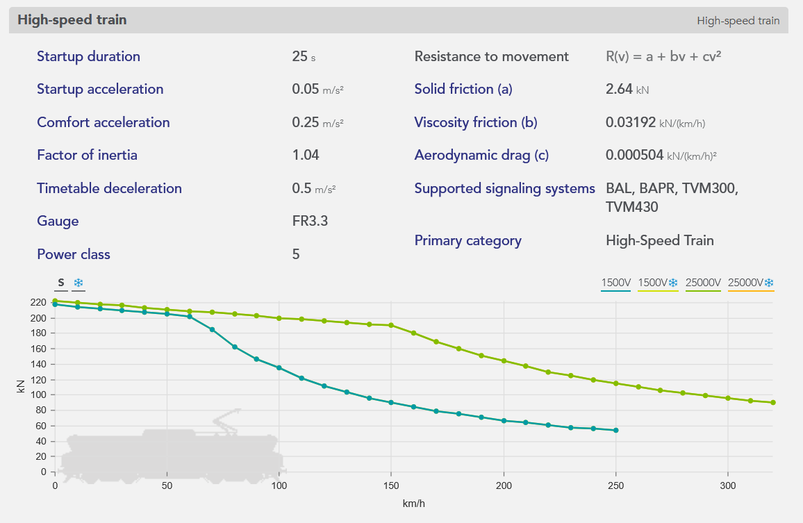
The characteristics of these rolling stocks have been calculated based on the average values of real rolling stocks within each category. Additionally, most of these models are designed to be compatible across various networks: they are primarily bi-mode (supporting multiple electric voltage and current supply types), which is not always the case for real-world rolling stocks.
An example of rolling stock, a high-speed train, is represented below, from the rolling stock editor of the application:
Open data
Since these rolling stocks are fictional (yet realistic), they can be freely used in projects beyond OSRD.
To access and use them in the application:
From the open-source playground: The rolling stocks are available by default.
From a locally launched application: Use the corresponding command in the README to import the test rolling stocks in your database.